Monday, November 30, 2009

Tuesday, November 24, 2009

Saturday, November 21, 2009
Power Supply spec'ed
Since a standard PC power supply does not provided the recommended voltage (7.5V) for our MegaBrite modules, I asked Andy Grahm to order this power supply:
https://www.jameco.com/webapp/wcs/stores/servlet/ProductDisplay?storeId=10001&langId=-1&catalogId=10001&pa=123415&productId=123415
We had considered using a hack to get get 7 volts from a PC power supply but I have not been able to confirm the amount of current with this technique. The above supply can source 20 amps.
I also ordered some additional MTA100 connectors so we can run 50 MegaBrites.
Drew
Thursday, November 19, 2009


more serial code with some explanation about the arduino SPI register
/* Ports and Pins
Direct port access is much faster than digitalWrite.
You must match the correct port and pin as shown in the table below.
Arduino Pin Port Pin
13 (SCK) PORTB 5
12 (MISO) PORTB 4
11 (MOSI) PORTB 3
10 (SS) PORTB 2
9 PORTB 1
8 PORTB 0
7 PORTD 7
6 PORTD 6
5 PORTD 5
4 PORTD 4
3 PORTD 3
2 PORTD 2
1 (TX) PORTD 1
0 (RX) PORTD 0
A5 (Analog) PORTC 5
A4 (Analog) PORTC 4
A3 (Analog) PORTC 3
A2 (Analog) PORTC 2
A1 (Analog) PORTC 1
A0 (Analog) PORTC 0
*/
// Defines for use with Arduino functions
#define clockpin 13 // CL - clock IN
#define enablepin 10 // BL - enable IN
#define latchpin 9 // XL - latch IN
#define datapin 11 // SI - data IN
// Defines for direct port access
#define CLKPORT PORTB
#define ENAPORT PORTB
#define LATPORT PORTB
#define DATPORT PORTB
#define CLKPIN 5
#define ENAPIN 2
#define LATPIN 1
#define DATPIN 3
// Variables for communication
unsigned long SB_CommandPacket; //megabrite command packet
int SB_CommandMode; //megabrite command mode
int SB_BlueCommand; //megabrite blue command
int SB_RedCommand; //megabrite red command
int SB_GreenCommand; //megabrite green command
//megabrite - Pd to Arduino serial data helper variables
int enableState;
int enaState;
//serial input for LED addresses
int LED;
//serial string input
int pd_String[15];
// Define number of MegaBrite modules
#define NumLEDs 3 //50
// Create LED value storage array [no. of leds][RGB channels=3]
int LEDChannels[NumLEDs][3] = {0};
// Set pins to outputs and initial states
void setup() {
//set data, clock, latch, enable pins for digital output
pinMode(datapin, OUTPUT);
pinMode(latchpin, OUTPUT);
pinMode(enablepin, OUTPUT);
pinMode(clockpin, OUTPUT);
//digital 0 (for latchpin) & digital 0 (for enablepin)
digitalWrite(latchpin, 0);
digitalWrite(enablepin, 0);
//SPCR is the Arduino SPI (Serial Peripheral Interface) Control Register
/*
The SPI control register (SPCR) has 8 bits, each of which control a particular SPI setting.
SPCR
| 7 | 6 | 5 | 4 | 3 | 2 | 1 | 0 |
| SPIE | SPE | DORD | MSTR | CPOL | CPHA | SPR1 | SPR0 |
SPIE - Enables the SPI interrupt when 1
SPE - Enables the SPI when 1
DORD - Sends data least Significant Bit First when 1, most Significant Bit first when 0
MSTR - Sets the Arduino in master mode when 1, slave mode when 0
CPOL - Sets the data clock to be idle when high if set to 1, idle when low if set to 0
CPHA - Samples data on the falling edge of the data clock when 1, rising edge when 0
SPR1 and SPR0 - Sets the SPI speed, 00 is fastest (4MHz) 11 is slowest (250KHz)
*/
//so here, we first enable the arduino SPI by setting SPE=1
//second, arduino is set to be the master
//third - setting SPI speeds to be fastest
SPCR = (1<<<< 2 bits free ===> shifted to next LED in chain
|||||||||| |||||||||| |||||||||| || = 32 bits
<<>> bitwise right shift
& bitwise AND
| bitwise OR
*/
SPDR = SB_CommandMode<<6>>4;
while(!(SPSR & (1<>6;
while(!(SPSR & (1<>8;
while(!(SPSR & (1<<<< sb_commandmode =" B00;" i =" 0;" sb_redcommand="LEDChannels[i][0]" sb_greencommand="LEDChannels[i][1]" sb_bluecommand="LEDChannels[i][2]" sb_commandmode="B01;" write="" to="" current="" control="" registers="" for="" int="" z="0;">< i =" 0;" j1 =" 0;" enablestate =" digitalRead(enablepin);"> 0)
{
enaState = Serial.read(); // receive data from Pd
Serial.println(enaState);
//digitalWrite(enablepin, enaState); // turn the leds on/off
//parse incoming string
//parseString();
/*for(int i=0; i<9; i++)
{
pd_String[i] = Serial.read();
Serial.print(pd_String[i], BYTE);
}*/
}
setLedColor(0, enaState, 1023, 1023);
//setLedColor(0, 1023, 1023, 1023);
setLedColor(1, 0, 1023, 1023);
setLedColor(2, 300, 0, 1023);
}
Direct port access is much faster than digitalWrite.
You must match the correct port and pin as shown in the table below.
Arduino Pin Port Pin
13 (SCK) PORTB 5
12 (MISO) PORTB 4
11 (MOSI) PORTB 3
10 (SS) PORTB 2
9 PORTB 1
8 PORTB 0
7 PORTD 7
6 PORTD 6
5 PORTD 5
4 PORTD 4
3 PORTD 3
2 PORTD 2
1 (TX) PORTD 1
0 (RX) PORTD 0
A5 (Analog) PORTC 5
A4 (Analog) PORTC 4
A3 (Analog) PORTC 3
A2 (Analog) PORTC 2
A1 (Analog) PORTC 1
A0 (Analog) PORTC 0
*/
// Defines for use with Arduino functions
#define clockpin 13 // CL - clock IN
#define enablepin 10 // BL - enable IN
#define latchpin 9 // XL - latch IN
#define datapin 11 // SI - data IN
// Defines for direct port access
#define CLKPORT PORTB
#define ENAPORT PORTB
#define LATPORT PORTB
#define DATPORT PORTB
#define CLKPIN 5
#define ENAPIN 2
#define LATPIN 1
#define DATPIN 3
// Variables for communication
unsigned long SB_CommandPacket; //megabrite command packet
int SB_CommandMode; //megabrite command mode
int SB_BlueCommand; //megabrite blue command
int SB_RedCommand; //megabrite red command
int SB_GreenCommand; //megabrite green command
//megabrite - Pd to Arduino serial data helper variables
int enableState;
int enaState;
//serial input for LED addresses
int LED;
//serial string input
int pd_String[15];
// Define number of MegaBrite modules
#define NumLEDs 3 //50
// Create LED value storage array [no. of leds][RGB channels=3]
int LEDChannels[NumLEDs][3] = {0};
// Set pins to outputs and initial states
void setup() {
//set data, clock, latch, enable pins for digital output
pinMode(datapin, OUTPUT);
pinMode(latchpin, OUTPUT);
pinMode(enablepin, OUTPUT);
pinMode(clockpin, OUTPUT);
//digital 0 (for latchpin) & digital 0 (for enablepin)
digitalWrite(latchpin, 0);
digitalWrite(enablepin, 0);
//SPCR is the Arduino SPI (Serial Peripheral Interface) Control Register
/*
The SPI control register (SPCR) has 8 bits, each of which control a particular SPI setting.
SPCR
| 7 | 6 | 5 | 4 | 3 | 2 | 1 | 0 |
| SPIE | SPE | DORD | MSTR | CPOL | CPHA | SPR1 | SPR0 |
SPIE - Enables the SPI interrupt when 1
SPE - Enables the SPI when 1
DORD - Sends data least Significant Bit First when 1, most Significant Bit first when 0
MSTR - Sets the Arduino in master mode when 1, slave mode when 0
CPOL - Sets the data clock to be idle when high if set to 1, idle when low if set to 0
CPHA - Samples data on the falling edge of the data clock when 1, rising edge when 0
SPR1 and SPR0 - Sets the SPI speed, 00 is fastest (4MHz) 11 is slowest (250KHz)
*/
//so here, we first enable the arduino SPI by setting SPE=1
//second, arduino is set to be the master
//third - setting SPI speeds to be fastest
SPCR = (1<
|||||||||| |||||||||| |||||||||| || = 32 bits
<<>> bitwise right shift
& bitwise AND
| bitwise OR
*/
SPDR = SB_CommandMode<<6>>4;
while(!(SPSR & (1<
while(!(SPSR & (1<
while(!(SPSR & (1<
{
enaState = Serial.read(); // receive data from Pd
Serial.println(enaState);
//digitalWrite(enablepin, enaState); // turn the leds on/off
//parse incoming string
//parseString();
/*for(int i=0; i<9; i++)
{
pd_String[i] = Serial.read();
Serial.print(pd_String[i], BYTE);
}*/
}
setLedColor(0, enaState, 1023, 1023);
//setLedColor(0, 1023, 1023, 1023);
setLedColor(1, 0, 1023, 1023);
setLedColor(2, 300, 0, 1023);
}
Wednesday, November 18, 2009
Where we're at so far.....
So far the panels are coming along, hopefully we can get the structures done by thursday.
Also I know we'll need more pine and there's one more trip to home depot.
A couple of the things we discussed about the project box were:
-How many switches it would need
-How big it would have to be to house the arduinos
-Where it would be placed
We decided on 1 switch and 1 potentiometer and Brittany found a nice project box at radio shack for $6.99 http://www.radioshack.com/product/index.jsp?productId=2062285
Also the only other thing on our list that we dont have yet is the power supply.
In total we will need 117 watts. Brittany also found a good power supplly for 19.99
The assembly team has decided to use wire metal as part of the super structure to make the dome part.
There was some discrepancy on what material to use to secure every thing since they were
afraid super glue would melt if the leds got too hot. So they decided on twisty ties.
Our order of wire came in, and we know they do work with the megabrite since we tested
them out. Me and Shaheer have finished assembling the wires (the first step) and will be
done with the second step by the end of Thursday.
That is all!!! Keep up the good work every one!:)
Tuesday, November 17, 2009
PD to Ardunio - Serial working :)
I've managed to send serial data to the arduino using the 'comport' object. Here's how you do it:

On the arduino IDE code:
add following lines to the void start() code:
void start()
{
Serial.begin(115200); // start serial communication to Pd
}
&void start()
{
Serial.begin(115200); // start serial communication to Pd
}
add following lines to the void loop() code:
void loop()
{
...
...
enableState = digitalRead(enablepin); // read the state of the enable pin
// send the value to the serial port (Pd)
if (Serial.available() > 0)
{
enaState = Serial.read(); // receive data from Pd
digitalWrite(enablepin, enaState); // turn the leds on/off
}
...
...
}
After I uploaded the code to the Arduino and opened the PD patch, I could toggle the LEDs on and off using a toggle.
Monday, November 16, 2009
Breakout Box Ideas

Based on our previous discussions of the breakout box that contains the two (2) arduinos and doubles as the control device, here is a basic diagram:
If we really want to get fancy, we can mount it inside the wall, so that the front panel is flush. Having the breakout box mounted outside of the wall may be a little more practical as it might be easier to get inside if necessary.
Wiring for Power

The red lines each emanate from + - , the power source. Each line actually represents two (2) wires, because each endpoint node needs a connection to power and ground.
Therefore, the rough math goes something like this:
Since each MegaBrite is approximately evenly spaced every two (2) feet we need (10+20+12+22+14+26+16+28) x 2 wires = 296 feet of power wire in the ceiling (assuming the power source is in the ceiling). If the power source is not in the ceiling, add (8) wire (x 2) pairs x 10 feet high, 160 feet more. For a grand total of 456 feet of wire for power.
Supercomputing 09 Update
I am in Portland for Supercomputing 09. I am here as a student volunteer and meeting folks from all over the US and the world. Just to give you a taste of what I am experiencing here, on Saturday I helped build SCinet, the fastest network in the world. On Sunday I attended several workshops including Principles and Practice of Application Performance Measurement and Analysis on Parallel Systems, and the Third International Workshop on High-Performance Reconfigurable Computing Technology and Applications. This morning I am attending the Ultrascale Visualization Workshop, and Sungwon Nam from the Electronic Visualization Laboratory at UIC is the first speaker. I have met already met up with several other UIC people from EVL. Although I can't stay for the bulk of the Keynote presentations (inlcuding former Vice President Al Gore) that continue through the week, the experience has been very rewarding. I will be back in action on campus Wednesday.
Friday, November 13, 2009
Thursday, November 12, 2009
Wednesday, November 11, 2009
Daisy Chaining works
The two megabrites are being operated only in single channel mode right now. I am working on controlling them individually. David and I had problems with the daisy chaining when we tried the example code given in the megabrite page. I am yet to use that code effectively to control them separately. Need to experiment on clock cycles and register shifting.
Here is the modified code that I got them working with: (removed no. of LEDs variable for now)
#define clockpin 13 // CI - ClockIN
#define enablepin 10 // EI - EnableIN
#define latchpin 9 // LI - LatchIN
#define datapin 11 // DI - DataIN
int LEDChannels[1][3] = {0}; //3 channels R,G,B for each LED
int SB_CommandMode;
int SB_RedCommand;
int SB_GreenCommand;
int SB_BlueCommand;
void setup() {
pinMode(datapin, OUTPUT);
pinMode(latchpin, OUTPUT);
pinMode(enablepin, OUTPUT);
pinMode(clockpin, OUTPUT);
SPCR = (1<
digitalWrite(enablepin, LOW);
}
void SB_SendPacket() {
if (SB_CommandMode == B01) {
SB_RedCommand = 120;
SB_GreenCommand = 100;
SB_BlueCommand = 100;
}
SPDR = SB_CommandMode <<>>4;
while(!(SPSR & (1<
while(!(SPSR & (1<
while(!(SPSR & (1<
while(!(SPSR & (1<
}
void WriteLEDArray() {
SB_CommandMode = B00; // Write to PWM control registers
SB_RedCommand = LEDChannels[0][0];
SB_GreenCommand = LEDChannels[0][1];
SB_BlueCommand = LEDChannels[0][2];
SB_SendPacket();
delayMicroseconds(50);
digitalWrite(latchpin,HIGH); // latch data into registers
delayMicroseconds(50);
digitalWrite(latchpin,LOW);
SB_CommandMode = B01; // Write to current control registers
SB_SendPacket();
delayMicroseconds(50);
digitalWrite(latchpin,HIGH); // latch data into registers
delayMicroseconds(50);
digitalWrite(latchpin,LOW);
}
void loop() {
LEDChannels[0][0] = 1023; //R
LEDChannels[0][1] = 640; //G
LEDChannels[0][2] = 0; //B
WriteLEDArray();
delay(200);
LEDChannels[0][0] = 640; //R
LEDChannels[0][1] = 0; //G
LEDChannels[0][2] = 1023; //B
WriteLEDArray();
delay(200);
}
--
Just upload this code to your arduino.
Plug in two megabrites in a daisy chain. (arduino to input pins & output pins on megabrite1 to input pins on megabrite2. output on megabrite2 is free without connections for now)
and plug in a 7.5 V powersupply to the arduino.
You'll see RG to RB blinks on both the LEDs synchronized every 200 ms.
--
Results:
Power dissipation was much better with this code, I don't know yet what caused the LEDs to nearly smoke last time (maybe some mistake in the code or circuit connections?). I think one of the megabrites started smoking after prolonged use last time around. These two seem stable(I was testing for heat, they never got as hot as when we tested them in class, maybe 9V is a bit too much) for a while(1 or 2 mins). They were extremely bright, brighter than when we saw in class.
Tomorrow's TODO:
x Test with IDE ribbon cable.
x Control both of the LEDs separately in different channels
x Add more shiftbrites to the chain and figure out power circuit
Some Wednesday Inspiration


I went to the Mobile Art && Code Conference at Carnegie Mellon University this past weekend and just wanted to share this LED Bridge that is new to their campus. It connects their Computer Science school to their Theater building.
Tuesday, November 10, 2009
Ceiling Tile Double-Check
Yes, basically, there are 45 positions of MegaBrites to contend with. My initial diagram is pretty close. Brittany floated an idea to also replace the 2+ tiles that are in front of the door. See you Thursday. Andy Graham was not here. I will email him right now to let him know we're starting to build on Thursday. We stashed our stuff in a back room since there was no one here to let us in.
Monday, November 9, 2009
Wires for FF and MF
I've checked the prices for the Wire with Pre-Crimped Terminals 5 - pack 24" (both Female-Female and Male-Female) on the Polou site. Some people requested at least 60-64 wires for each bundle. One wire costs $4.49, but for 10 wires each, they're $4.04. Here is the available quality and colors I've found and calculated.
And here's how much it costs to get 64 wires for MF and FF
Since they had less than 60 to 64 wires, I had to make a second order to make a equal order by buying a second color set for both FF and MF.
Here's how much it would cost if getting 60 wires for MF and FF
| Product | Quantity | Price | Total Price | |||
|---|---|---|---|---|---|---|
| $4.04 | $84.84 | ||||
| $4.49 | $26.94 | ||||
| $4.04 | $218.16 | ||||
| $4.04 | $157.56 | ||||
| Subtotal | $487.50 | |||||


| Product | Quantity | Price | Total Price | |||
|---|---|---|---|---|---|---|
| $4.04 | $101.00 | ||||
| $4.04 | $40.40 | ||||
| $4.04 | $218.16 | ||||
| $4.04 | $157.56 | ||||
| Subtotal | $517.12 | |||||
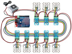
Simple Wiring Diagram

OK. Here is the simple wiring diagram, based on my previous post. All the megabrites are addressed in a chain. These lines represent the 6-wire ribbons (each are spaced approximately two feet apart). We do need a little wiggle room, since we haven't finalized the exact panel design (at least where on the panel the MegaBrites will sit). In either case, there won't be much variation, I think, from this. The MegaBrite documentation also suggests that each MegaBrite should get its own power. I am assuming that we can just run a wire (in parallel) to all the MegaBrites according to this same scheme + to -, + to - on the screwd0wn pins. Y'all with me?
Which means we'd have to run that same wire back to ground. NOTE: all the above assumes that the Arduino is attached to position 10 near the first megabrite. Here we'd also have a control knob (dimmer) and the on/off switch and a USB cable sticking out of the wall for the programming mode. Whoa- there's a patch panel for ya.
Sunday, November 8, 2009
I counted 45

56 or 45?
Somebody please have a look at this diagram and tell me if I am right or not.
Last week when we were talking about 56 MegaBrites, I think we were going by 28 panels x 2. But If you look at my diagram, that is the wrong arithmatic. Not all panels will have 2 MegaBrites, the small panels will have just 1 each.
So its more like (2 x 17) + 11 = 45
Thursday, November 5, 2009


Subscribe to:
Posts (Atom)